Commercialization of technologies to produce faster temperature ramps in GC have been some of the few GC advances in recent decades. This article will take a look at the utility and ultimate areas of practical application for these technologies.
Leonid Blumberg and I (1) proposed that the optimal normalized heating rate in temperature programmed GC is approximately10 oC/t M. This figure was presented as a general guideline for providing a reasonable compromise between overall analysis time, time for solutes to interact with the stationary phase, and reasonable detectability (related to peak width). The reason we related the ramp rate to holdup time is because it is the primary relationship that describes the programmed temperature history of a solute through a column. If one uses a short column with one half the tM of its larger counterpart and the same ramp rate in oC/min (that is the parameter available to you to set), the solutes would experience a different temperature history by the time they elute from the columns. The solutes in the shorter column would have experienced a lower average temperature than those in the longer column. Why does this matter? With changes in average temperature, there can also be changes in selectivity because selectivity is a function of temperature. This is why in Method Translation (2) one keeps the value of oC/tM constant when changing column sizes and carrier gas flow rates or types.
In the case of very fast normalized ramp rates, the solutes have no time to interact with the stationary phase. They will transition rapidly from a highly-retained state at low temperature to a non-retained state, after which they move through the remainder of the column at carrier gas velocity. So in essence, active partitioning might occur in only a fraction of the length of the column and the rest of the column serves no purpose other than to broaden the peaks because of longitudinal diffusion (a negative impact).

Figure 1
One requirement for fast heating is that the thermal mass of the objects being heated is low. Heating of low thermal mass columns has been accomplished in many ways including passing current through a metal or metal coated capillary column, by intertwining heating and sensing wires with the coils of the fused silica tubing (3-4), by using an etched column in a small silicon or metal wafer, and by using a clam shell oven just big enough to cover the column or etched wafer. Each approach has advantages and disadvantages. Any approach might be reproducible, which is OK for analyses that are individually calibrated and for which columns rarely need to be replaced. However, for the accuracy necessary to make methods easily transferrable between systems and after column maintenance (or replacement) the heat and temperature sensing feedback loop need to be tightly controlled and tightly coupled to the column.

Table 1
Most resistively heated column approaches can ramp column temperatures at more than 600 oC/min, whereas standard GC air-bath ovens are limited to an upper rate of 120 oC/min or so (oven temperature depended; heating becomes slower at higher temperatures). With a standard 25 m x 250 µm id column at optimal flow-rate (1 mL/min), the holdup time at 150 oC is approximately 1.35 min. So at a 10 oC/t M, this would be 13.5 oC/min, which is in the range of what people normally use for sample analyses spanning a wide temperature range. However, at 600 oC/min, this amounts to a normalized heating rate of approximately 445 oC/t M, which clearly would not provide much opportunity for separation of a complex sample.
 Figure 2
So what are very fast program rates good for? It is rarely how fast they can ramp. A side benefit of the low thermal mass is that it takes less power to heat the column. This makes low thermal mass approaches more suitable for portable GC instruments (whether isothermal or programmed temperature). In theory, lower thermal mass should also mean faster cool down, which in turn would provide significantly faster cycle times and more samples could be analysed in a given time frame. However, cool down time is quite dependent on the implementation - fast cool down usually requires a high flow of air around the column. Some designs impede air flow between coils or around the chip as is the case with some chip designs (which are more typically designed for isothermal analyses). In the case of the LTM module (Agilent Technologies, Inc.), the longer the column length, the longer it takes it to cool down (whereas in an active air bath oven, cool down time has little to do with column length). At a length of approximately 25 m for a 250 um column, cool down time of an Agilent LTM column approaches that of the 7890 GC turbo air bath oven with any size column in it.
Another area of application that is quite interesting for low thermal mass columns is in multidimensional separations. In these cases, having a separate temperature control zone for each column provides the ability to tune each separation independently. A nice approach is to keep the second low mass column at a temperature low enough to trap several heartcuts prior to independent temperature programming and separation on the second column. In these portable or multidimensional applications, the low thermal mass designs are not used at extremely fast program rates; they are either isothermal or within the 5-25 oC/tM range.
However, there are a couple applications where the very fast normalized heating rates can be beneficial: those that (1) require little or no peak separation and (2) cover a broad boiling point range of sample components. Two examples of this are simulated distillation and total petroleum hydrocarbon (TPH) analysis.

Table 2
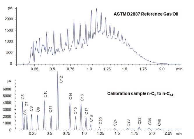
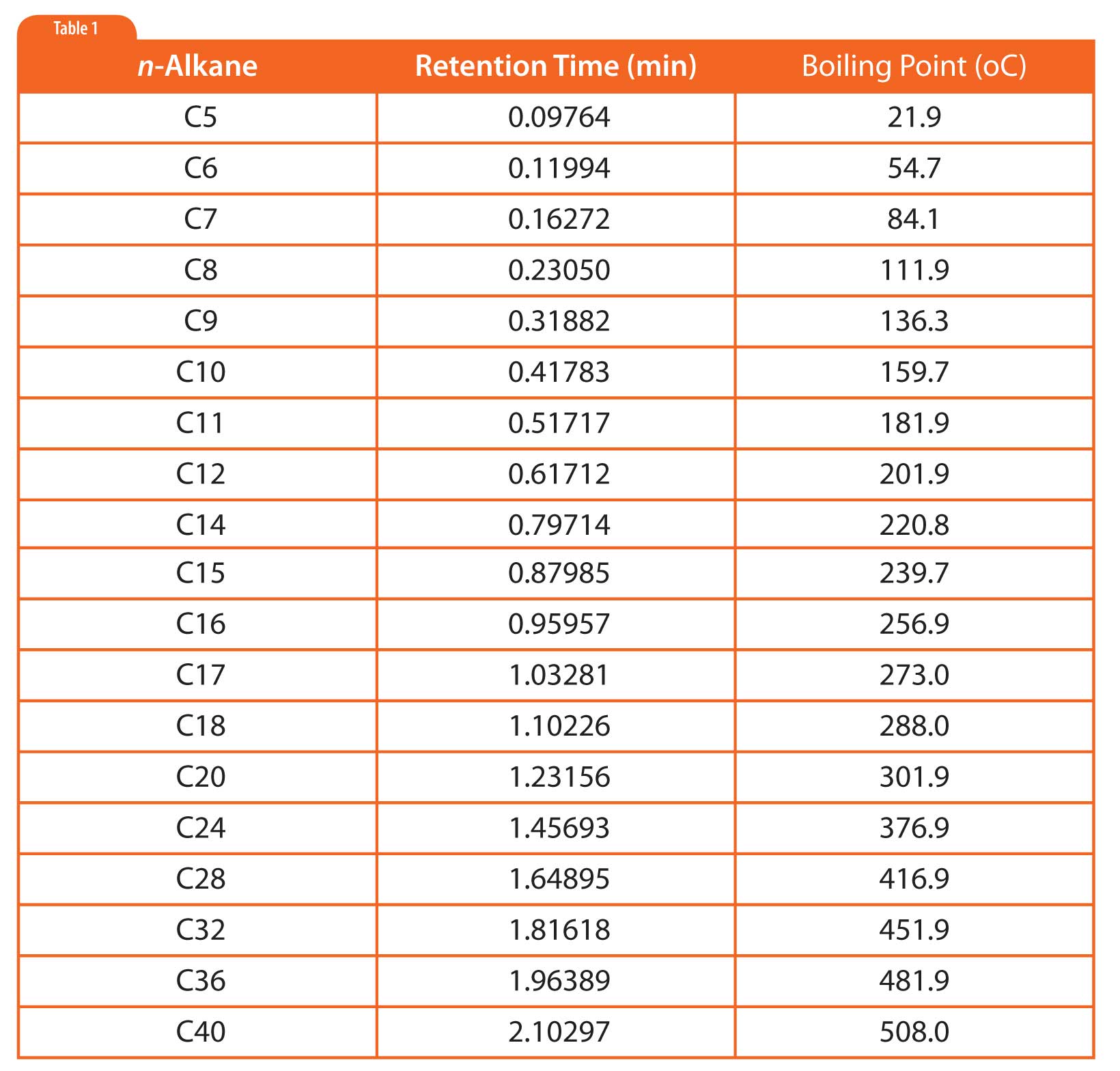
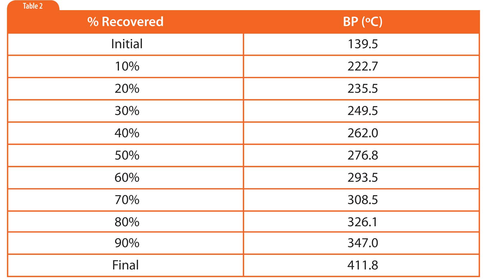
In simulated distillation (used in oil refining), one generates a boiling point versus retention time calibration based on normal alkanes as shown in Figure 1 and Table 1 (5). Then one uses area-percent slices of the sample chromatogram to determine the boiling point at which given percentages of the sample had eluted, as shown in Table 2. There is no need for or interest in separating individual components.
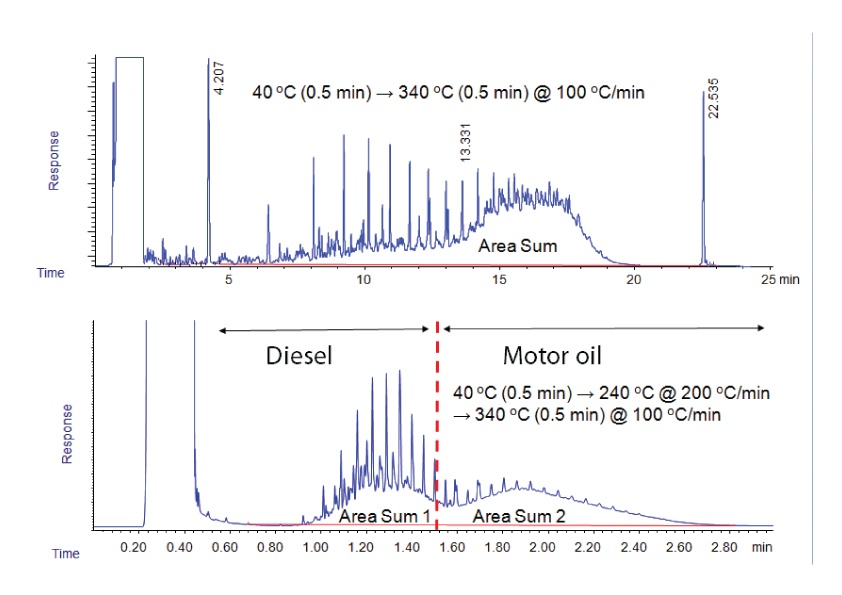
TPH analysis is even simpler. The goal in TPH is simply to estimate the total hydrocarbons present by using either a single sum of the total response, or by dividing area response into two categories (low end = diesel range and high end = motor oil range), as shown in Figure 2. TPH analysis is commonly used to monitor the leach rate and direction of leaks from underground storage tanks. In both the simulated distillation and TPH examples, very fast temperature ramping has been shown to yield comparable results to the more traditional ramp rates. But still, even though faster than conventional oven ramp rates, the fastest possible rates are not used.
In summary, there is a place for very fast ramping, but it is limited. The ultimate sustainable value of low thermal mass approaches to column heating is not in the fast ramp rates, but in the lower power consumption and potentially the faster cool down times.
References
1. Optimal heating rate in gas chromatography, L.M. Blumberg and M.S. Klee, J. Micro. Sep. , 12 (2000) 508–514
2. Method Translation and Retention Time Locking in Partition GC, L.M. Blumberg and M.S. Klee, Anal. Chem. , 70 (1998) 3828-3839
3. Low Thermal Mass Gas Chromatography: Principles and Applications, J Luong, Ronda Gras, Robert Mustacich, Hernan Cortes, J, Chromatogr Sci. , 44(5) (2006) 253-261
4. US Patents, R. Mustacich et al, 5,782,964, 6,209,386, 6,217,829, 6,490,852, 6,682,699
5. High Throughput Mineral Oil Analysis by GC-FID using the Agilent Low Thermal Mass System, F. David, K. Jacq, and R. Firor, Agilent publication 5990-9104EN
6. Fast Hydrocarbon and Sulfur Simulated Distillation Using the Agilent Low Thermal Mass System on the 7890A GC and 355 Sulfur Chemiluminescence Detector, CX Wang, R. Firor, P. Tripp, Agilent publication 5990-9104EN
This blog article series is produced in collaboration with Dr Matthew S. Klee, internationally recognized for contributions to the theory and practice of gas chromatography. His experience in chemical, pharmaceutical and instrument companies spans over 30 years. During this time, Dr Klee’s work has focused on elucidation and practical demonstration of the many processes involved with GC analysis, with the ultimate goal of improving the ease of use of GC systems, ruggedness of methods and overall quality of results. If you have any questions about this article send them to techtips@sepscience.com


