Ion mobility spectrometry (IMS), by itself has found a niche in many areas including security screening, environmental monitoring, military applications, and analytical laboratory use. The technique is not mass spectrometry, however it is related to MS by the fact that IMS does perform separation of ions. IMS is available coupled with mass spectrometry as a hybrid instrument (IMS-MS). Therefore it is important for the modern mass spectrometrist to have some background in the fundamentals of the technique.
Fundamentals of IMS
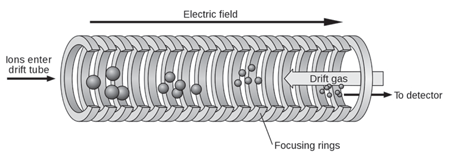
IMS separates ions based on their mobility in the gas phase in a carrier buffer gas and an applied electrical field. The carrier buffer gas flows in opposition to the direction of flight of the ions. Separation is not based on mass-to-charge ratio as it is in mass spectrometry but rather on a combination of the ion’s mass, charge, size, and shape. It is somewhat analogous to electrophoresis in that ions move in response to the applied electrical field but their movement is impeded by the counter-flow of buffer gas. The greater the cross-sectional area of the ion, the greater the number of collisions with the buffer gas and therefore the greater the time it takes the ion to travel a given distance. Stated another way, ions of greater cross-sectional area will arrive at the detector later than those of lesser cross-sectional area. Differences in arrival time is the basis for separation. It is important to note that the ion’s mass and it’s cross-sectional area are not related. Ions of the same mass but of different molecular shape may be separated by IMS. Figure 1 is a schematic of a simple time-of-flight IMS device.
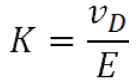
The ion mobility (K ) under a fixed set of conditions is the proportionality factor between the ion’s drift velocity, vD , and the applied electrical field E :

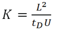
Experimental determination of ion mobility (K), in a drift tube of length L with an applied electrical field potential U is accomplished by measuring the ion’s drift time, tD :

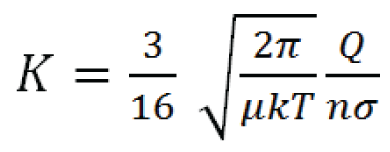
K in a constant, low-power electrical field is calculated by the Mason equation:

In the equation, Q is the charge on the ion, n is the drift gas number density (related to pressure and flow), μ is the reduced mass of the ion and buffer gas molecule*, k is the Boltzmann constant, T is the temperature of the drift gas, and σ is the collisional cross-section of the ion. Therefore increasing charge on the ion; decreasing the cross-sectional area of the ion; or decreasing buffer gas temperature, pressure, or flow will result in increased ion mobility. Note that in low potential electrical fields the ion mobility is independent of electrical field strength.

Figure 1: Schematic diagram of a simple time-of-flight ion mobility spectrometer (TOF IMS). (Wikipedia Creative Commons Attribution - Share Alike 3.0)
Low field strengths are used for TOFIMS devices of the type shown in Figure 1 and also for traveling wave IMS. Separation in these devices is closely related to mass-to-charge ratio and therefore combination of simple IMS devices with MS has no particular advantages in resolving similar analyte species. However, at higher applied field strengths, the ion mobility varies with the field strength and becomes a useful separation enhancement tool for mass spectrometry.
Field-Asymmetric Ion Mobility Spectrometry (FAIMS)
The separation power of IMS can be enhanced by oscillating the applied electrical field from high to low and back again in an asymmetric fashion. This is due to the fact that ions show different K values in high- versus low-potential electrical fields. Oscillating the field therefore refines the selectivity between ions which have similar low-field mobility values (see Figure 2).

Figure 2: Ion mobility values for three ions (represented by different colors), are similar at low dispersion field (DF) strength but show different behaviors and are easily separated at high DF values.
The buffer gas in FAIMS carries ions between two closely spaced electrodes which form the IMS cell. The oscillating electrical field is referred to as the separation or dispersion field (DF). The dispersion field is applied between the cell electrodes and is perpendicular to the gas flow. Ions therefore drift sideways towards one electrode or the other and will eventually crash into the electrode. To counteract this drift a DC compensation field (CF) can be applied which modifies the trajectory of the ions as they pass through the IMS cell. At a particular CF strength only ions of a selected mobility behavior emerge from the end of the cell. The DC compensation voltage can be varied to provide a scanning function similar to that of a transmission quadrupole mass spectrometer, i.e. ions are allowed to pass through the device one-at-a-time based on their mobility behavior. This technique is referred to as Field-Asymmetric Ion Mobility Spectrometry (FAIMS) or Differential Mobility Spectrometry (DMS). Operation of a FAIMS device is shown schematically in Figure 3.

Figure 3: Schematic representation of a FAIMS device. Ions drift in the carrier gas between the two electrodes. The asymmetric dispersion field (DF) causes ions to drift toward one electrode or the other based on their individual mobility behavior in high electrical fields. Application of a fixed compensation voltage (CF) allows selected ions to pass through the device as shown by the red trace. By scanning the CF all ions entering the device are transmitted one at a time. Addition of a mass spectrometer (MS) on the outlet side of the FAIMS device results in a powerful hybrid instrument for enhanced separation of closely related ionic analytes and reduction of background interferences.
When two separation processes rely on significantly different characteristics of the analyte to effect the separation, the two processes are said to be orthogonal . Separation of ions in FAIMS/DMS devices is not closely related to their m/z ratio. Therefore FAIMS and MS are orthogonal separation techniques and useful hybrid instruments can be constructed with these two devices or with the addition of a chromatographic front-end to add even more separation power. Chromatography-FAIMS-MS hybrid instruments provide enhanced ability to separate closely related ionic analytes and/or to greatly reduce background ion interference. In some applications volatile chemical reagents can be introduced to the gas stream which interact with the analyte via ion-molecule reactions similar to chemical ionization in MS. These chemical interactions modify the analyte ion mobility to provide further resolution improvements.
A DMS device was introduced by Varian in 2005 for use as a detector on their MicroGC product. In more recent years, other vendors have now introduced FAIMS/DMS add-ons to existing LC/MS products.


