Selecting an appropriate inlet liner from the myriad available liner choices is a daunting task, especially when there is little qualified technical information about what differentiates them in terms of actual performance. Here we start discussing aspects of GC inlet liner design and associated selection criteria.
Inlet liners are “consumable” instrument parts, meaning that they are replaced on a regular basis – even daily for some applications. Usually made from borosilicate glass, liners provide a more inert flow path for samples to traverse than the metal inlet weldment, and they can protect columns by retaining non-volatile sample components that would otherwise degrade system performance.
The dimensions and design aspects of liners are constrained by the design of the inlet weldment as well as the specific application for which they will be used. There is no one liner that is best for all applications, so it is important to understand what the important liner variables are and how they might impact results.
- Liner choice can have a significant impact on method performance issues such as:
- Decomposition
- Flashback (preferential loss of volatiles, contamination leading to carryover, ghost peaks, rolling baseline …)
- Peak broadening
- Discrimination
- Low precision
Most of the above issues are exacerbated by hot inlets; the hotter the inlet, the worse the problem (as opposed to programmable temperature inlets wherein the sample is introduced at low temperatures). Issues 1-3 are greatly impacted by the residence time of the sample in the hot inlet – the longer the residence time, the worse the problem. Residence time is a direct function of the liner volume and the total flow rate through the inlet. Although decomposition is still possible with packed column inlets , flow rates are typically high (20-30 mL/min) and all of the flow goes directly into the column (no split), so residence time is low and the other issues are not as pronounced as with capillary column inlets. There also is not much you can do to improve things if the is a problem. If decomposition were a concern for a given sample, you would likely not be using a packed column for the analysis anyway. Based on these considerations, the discussion on liners will focus on capillary column inlets.

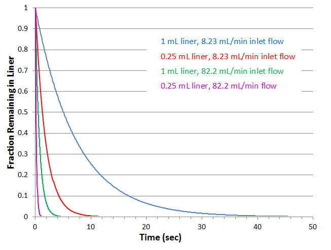
Figure 1: Transfer of sample from inlet as a function of liner volume and flow rate through the inlet approximating on an exponential dilution model. Actual transfer is somewhere between plug flow (faster) and exponential. Analyte volatility and its interaction with the liner (and glass wool) also influences transfer (less volatile and more polar interact more and transfer slower).
When considering flow through the inlet, remember that the volumetric flow through the inlet is NOT the volumetric flow suggested by the setpoints. Most GC setpoints, including column and a split flows are stated in terms of Standard Conditions : 25 °C and 14.7 psia. Residence time in the inlet relates to the local flow within the inlet, which is the flow rate at inlet pressure and temperature. For example, if the setpoint total flow (column + split flow rate) through a split inlet liner were 20 mL/min (SCCM), the corresponding inlet pressure were 48 psig (62.7 psia) and temperature 250 °C (523 °K), the flow rate through the inlet would actually be:

If the liner volume were 1.0 mL, then the required time to remove solvent vapors would be at least:

Since the liner is usually an open space, the sample vapors are diluted as they are transferred, extending transfer times to that of a pure exponential dilution, as illustrated in Figure 1. For the above scenario then, transfer of 99.9% of the sample vapors could take up to 50 sec.
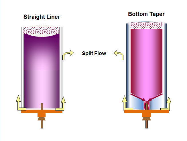
Complicating matters further, actual transfer rates are related to analyte volatility and polarity. Once in the gas phase, molecules move very quickly and will contact the liner surface where they can interact. The less volatile (late eluting compounds) or more polar the components, the more they will interact with the surface, the longer they will remain in the inlet, and the more time they will spend close to the wall, as illustrated by the shading in Figure 2a. Slower transfer of low volatility solutes is somewhat self-correcting because they are likely to refocus once they reach the head of the column. However, early eluting peaks will not refocus, so if they are uncharacteristically wide, that means that transfer from the inlet is too slow and a liner with a smaller internal volume and/or a higher split flow rate is probably required. The magnitude of the potential improvements are illustrated by the additional curves in Figure 1.

Figure 2: Sample vapors fill liner space but heavier components can preferentially interact with liner wall and then do not quantitatively migrate back to the center of inlet where the column entrance is, causing high end discrimination. Bottom tapers force all components back to the middle for more representative transfer to the column. Tapers also reduce exposure of sample components to the metal base of the inlet.
The preferential travel of less volatile components down the wall of a liner results in high-end discrimination. This type of discrimination is inlet temperature dependent; higher inlet temperature reduces surface interactions, reducing high-end discrimination. However, higher temperatures can cause new problems. A better solution is to use a liner with a taper at the bottom and install the column within the taper. Because of the taper, all vapors are funneled in close proximity to the column entrance and discrimination is reduced. The closer the diameter of the taper to the outer dimension of the column, the less the potential discrimination. In addition, the taper reduces exposure of sample vapors to the metal bottom of the inlet where the possibility of decomposition and contamination is higher.
When using a tapered liner, it is important to position the tip of the column near the center of the taper. If the column tip protrudes above the taper, potential discrimination and reproducibility improvements are negated. If the tip is below the taper, discrimination improvements are reduced and more sample is exposed to the inlet base. Liner manufacturers will usually provide guidance as to appropriate installation depth for proper placement of the tip within the taper. If they do not or you are unsure, follow the following process (once per liner design):
- Cool and vent the system.
- Gently remove and retain any glass wool in the liner.
- Install the liner in the manner you normally would but leave the top open.
- Push the end of the column through a spare inlet septum and move the septum down approximately 4-5 cm.
- Place nut and ferrule on the column. Trim approximately 1 cm from the end.
- Install column into the inlet with the end extending 1.5 cm above the ferrule. Tighten the nut just enough to hold the column in place but not so tight that it seizes on the column.
- Delicately insert a narrow, clean, low mass rod, stick, or whatever, with a flat end into the inlet until it rests on the top of the column. I use an upside down wooden cotton swab.
- Loosen the column nut and pull the column out slowly while watching the stick move down. Stop when the stick stops moving. Move column up/down slightly to verify that the stick has bottomed out.
- Tighten column nut and slide septum up the column until it rests against the bottom of the column nut.
- Loosen nut and remove column/nut ferrule together.
- Measure the distance from the top of the ferrule to the tip of the column. This represents the position of the column flush with the top of the taper.
- Remove the liner and measure the distance from the top of the taper channel to the middle of its linear section (do not include any funnel taper at the base). Subtract this number from the number you got for the column height above the ferrule. The result is the proper installation height that will position the column end at the half way point in the linear portion of the taper.
- Push the nut and ferrule up using the septum so that the protruding length of column is at the newly determined correct height.
- Replace the liner wool in its original position in the liner, reinstall everything, turn on flows, purge, heat and you are ready to go.
I believe that one should ALWAYS use a liner with a bottom taper when doing liquid sample introduction (more apt to have low boilers and active compounds). When doing gas injections (e.g., valves, headspace, purge & trap), using a tapered liner may not improve things, but it won’t hurt.
In the next part we continue the discussion of the influence of liner design and choices on performance.
This blog article series is produced in collaboration with Dr Matthew S. Klee, internationally recognized for contributions to the theory and practice of gas chromatography. His experience in chemical, pharmaceutical and instrument companies spans over 30 years. During this time, Dr Klee’s work has focused on elucidation and practical demonstration of the many processes involved with GC analysis, with the ultimate goal of improving the ease of use of GC systems, ruggedness of methods and overall quality of results. If you have any questions about this article send them to techtips@sepscience.com


