This article will discuss split injections with a hot split/splitless inlet. This is the most popular inlet and sampling mode for capillary GC. The focus will be on the basic concepts and flow paths. Later articles will cover liner choice, optimization and other practical considerations.

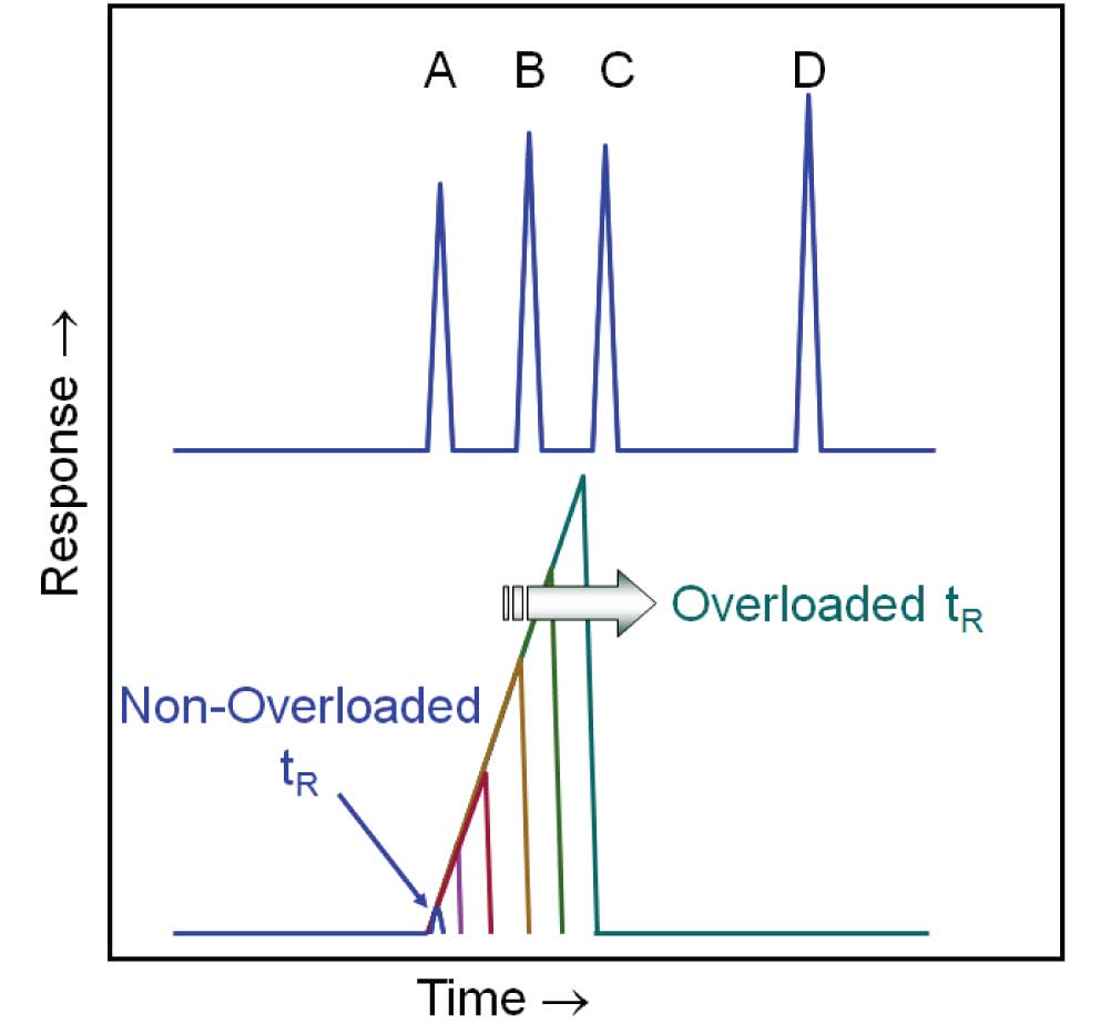
Figure 1: Capillary columns are easily overloaded with sample causing distorted peaks (usually fronted). The lower chromatogram illustrates the shift in retention time and the ever-widening peak width as amount of peak “A” on column is increased. It is clear by referring to the top chromatogram that an overloaded peak A would totally obscure peak B and at some point peak C.
Capillary columns have very low sample capacities compared with packed columns. Introducing too much sample causes peaks to become wide and triangular (distorted, fronted, misshapen). We call this overloading the column. The wide peaks can overlap neighbouring peaks that otherwise might have been resolved, as illustrated in Figure 1. In addition, the height of overloaded peaks scales differently than with lower loadings. This makes calibration curves based on peak height more complicated. Lastly, the retention time shifts (usually to later times) so the peak can fall out of retention time windows used for identification and integration events.
So, it is necessary to keep the amount of sample that reaches the capillary column very low (e.g., 10 ng, 10-8 g, per component). However, it is difficult to accurately and reproducibly inject less than a few tenths of a microliter (0.1 µL, 10-7 L, ≈ 10-4 g). Split inlets were designed to solve this problem; to allow manageable volumes (e.g., 1 µL) of liquid sample to be injected while keeping the amount that reaches the column in the target range. This and the following benefits combine to make the split inlet the most versatile and widely used sample introduction interface for capillary column GC. The split inlet is very flexible, it
- can easily be adjusted in response to changes in sample concentrations, injection volumes, methods, etc. to balance needs of sensitivity and minimal overloading
- provides the narrowest initial peak widths (important for fast GC and separation of early eluting peaks)
- is the preferred interface for auxiliary sampling devices such as headspace and purge & trap
- minimizes the time that sample stays in the hot inlet (decreases probability of decomposition)
- minimizes affects of solvent on peak shapes (negligible solvent recondensation in column)
- can be used to inject neat (undiluted) samples
- protects the column from non-volatile sample components (less column contamination because of dirty samples)
- is more forgiving of solvent expansion issues during evaporation than splitless mode.

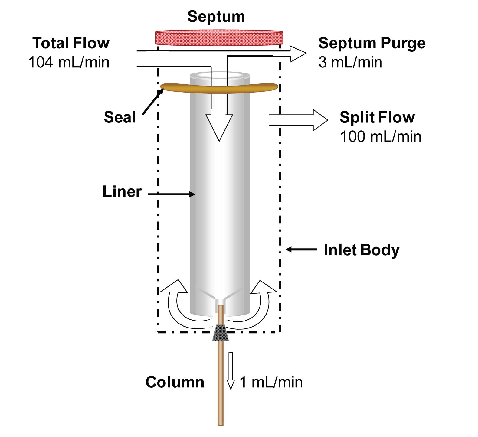
Figure 2: Flow of carrier gas during split injections. Flows shown are typical and correspond in this case to a split ratio of 100.
During split injections, most of the sample is vented out the split vent line and only a small fraction enters the capillary column. Figure 2 maps the flow paths in a typical configuration of split splitless inlet in split mode. Carrier gas flows to the inlet through a single tube where it is split inside the inlet into several pathways. A small amount of the flow typically passes under the septum to prevent septum off-gases and contamination from reaching the column. This is usually a preset amount of flow in the 2-10 mL/min range. Most of the flow travels down the inside of the inlet liner to the bottom where it is divided again. Some of the flow goes into the column (at the column flow rate) and the remainder travels down, around the bottom of the liner and then up between the liner and the inlet body before moving out the split vent.
Let’s run through the example flow rates shown in Figure 2. A total flow of 104 mL/min of carrier gas is fed into the inlet. 3 mL/min flows under the septum at the top of the inlet and out the septum purge line.
The remainder of flow (101 mL/min) flows down the liner, ostensibly carrying sample vapours toward the column. At the base of the liner (shown here properly positioned in the taper of the liner) is the column. 1 mL/min travels into the column, and the remainder (100 mL/min) travels around the outside of the column, around the base of the liner, up the sides of the liner, through an activated carbon trap, a backpressure controller, and finally out the vent. The trap helps to protect the backpressure controller from vented sample components. In this example, 100 mL/min flows out the split vent.
It is important to be aware of the split ratio; the ratio of split vent flow to column flow:
split ratio = split vent flow/column flow
In our example, the split ratio would be 100 (100:1). One might be tempted to use the inverse (1/100) as a measure of how much sample reached the column (e.g., 1%), which is fine at higher split ratios. However, one should realize that accurate calculation of the fraction of sample reaching the column is more accurately determined with the following relationship.
fraction reaching column = column flow/
(column flow + split flow)--PageBreak--
In our example, the fraction of sample entering the column would be .0099 (1/101) or 0.99% which is not significantly different than the estimate from split ratio. But for smaller split ratios it can be significant, the more accurate equation should be used.

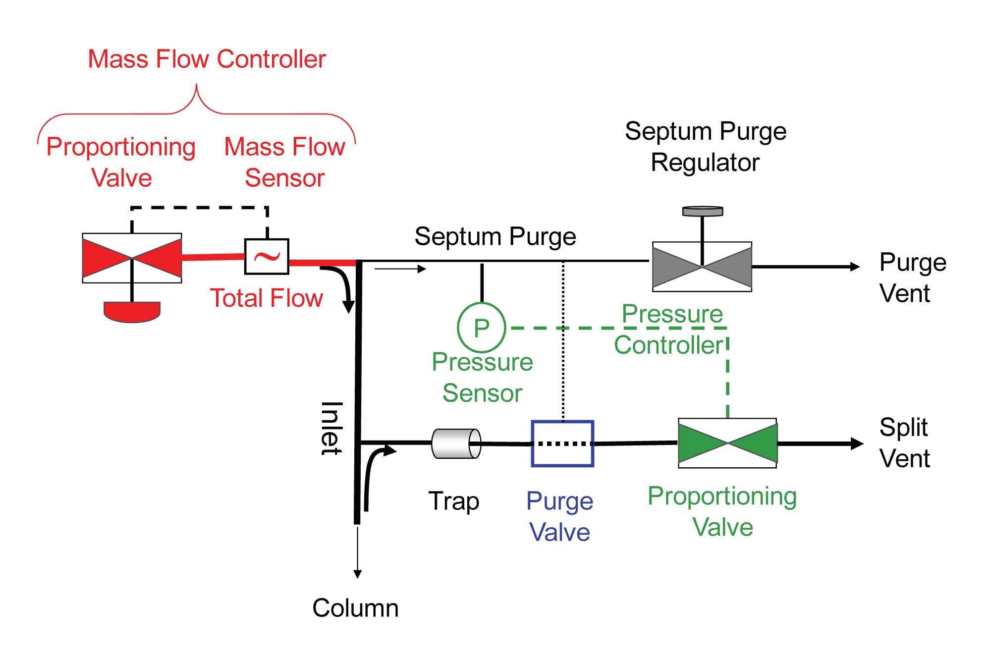
Figure 3: Flow and pressure control schematic for a typical electronically controlled split inlet. The mass flow sensor is used in a feedback control loop (red) to control total flow to the inlet – this is the electronic equivalent to a mechanical mass flow controller. A pressure sensor located on the septum purge line is used in a feedback control loop (green) with the backpressure controller on the split vent line to control inlet pressure. The purge valve (blue) is in the split (purge) mode.
In Figure 3, the flow and pressure control elements of a typical electronically controlled split inlet are shown. Electronic pneumatic control is obviously a better choice than mechanical in terms of ease of use, repeatability, automation, precision and electronic documentation. Starting from the left side of Figure 3, a mass flow controller is shown controlling the total amount of flow to the inlet through a closed-loop feedback control loop between a proportioning valve and a mass flow sensor.
A septum purge regulator controls the septum purge flow. It can also be mechanical or electronic. The advantage of using an electronic flow controller (or at least an electronic on/off solenoid with a mechanical controller) is that the septum purge can be turned off (1) during leak checking or automated column calibration and (2) during splitless injections (all to be discussed in later articles).
In this example, an inlet pressure sensor or gauge is located just before the septum purge flow regulator line teed into the septum purge line. It is there because (1) the septum purge gas has much less sample vapours/contamination than the split line does and (2) the low flow rate in the line means less chance of there being a pressure drop than with the high flow line leading to the inlet, leading to inaccurate pressure measurement.
Finally, the split flow travels out a larger i.d. tube, often heated by the inlet heater block to keep vented sample material from condensing in the line, to a trap where (hopefully) the vented sample components are trapped, and then through a trap, a proportioning valve and out to vent. Pressure control is accomplished with a feedback loop between the pressure sensor and the proportioning valve.
That does it for general flow and control concepts related to split inlets. In subsequent articles I will discuss more practical aspects of the split injection process.
This blog article series is produced in collaboration with Dr Matthew S. Klee, internationally recognized for contributions to the theory and practice of gas chromatography. His experience in chemical, pharmaceutical and instrument companies spans over 30 years. During this time, Dr Klee’s work has focused on elucidation and practical demonstration of the many processes involved with GC analysis, with the ultimate goal of improving the ease of use of GC systems, ruggedness of methods and overall quality of results. If you have any questions about this article send them to techtips@sepscience.com


