Although gas chromatography has many positive attributes as an analytical tool, its incompatibility with labile and active compounds is certainly one of its biggest weaknesses. Here we discuss evidence of sample decomposition and what we might do to improve the results.
Compounds with weak bonds and/or active functional groups are most prone to problems with GC analysis. The elevated temperature and the passive nature of the mobile phase (inert gas) aggravate the situation. When degradation is involved, it can be caused by temperature alone or by a combination of temperature and exposure to catalytic surfaces – which I include under the umbrella of “active sites”.
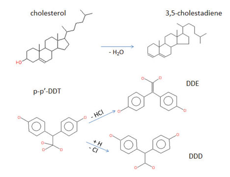 Figure 1: Examples of simple degradations that yield smaller, less retained compounds.
Decomposition of a parent compound is usually characterized by formation of one or more smaller, more stable reaction products such as those shown in Figure 1. However, more complex forms of degradation are also possible, leading to formation of multiple degradation products, some of which do not chromatograph well or may even not elute from the column.
One of the most problematic areas in a GC that lead to sample degradation is hot inlets; especially in the splitless mode where residence times are high. If degradation occurs in the inlet, and the degradation products are well behaved chromatographically, then sharp peaks will be generated for the products as illustrated in figure 2. In this example, the parent compound degraded to equal amounts of two daughter compounds. The presence of a small peak for the parent indicates that the degradation was not complete and offers some hope that adjustment of setpoints and minimization of activity in the system might improve if not eliminate the decomposition.
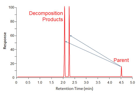
Figure 2: Fast degradation in a hot inlet that created two degradation product peaks with earlier elution times than the parent compound.
Figure 3 illustrates that in some cases, later-eluting compounds can be formed when a compound “decomposes” in the inlet. In this example, a monomer reacted to form a series of larger compounds that eluted at later times. Of course one should assume that the polymerization did not stop with just the peaks that were seen and that the inlet and column are contaminated by even larger oligomers that did not elute.
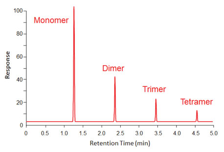
Figure 3: Fast polymerization occurring in a hot inlet, creates larger compounds with sharp peaks at correspondingly higher retention times.
So, decomposition (or reactions) that happen in the inlet generally produce normal looking peaks at the correct retention times of the individual decomposition products because it happens during sample introduction and the products experience the same focusing phenomena and chromatographic conditions as do other sample components. On the other hand, decomposition that happens on (or along) the column can produce some ugly messes.
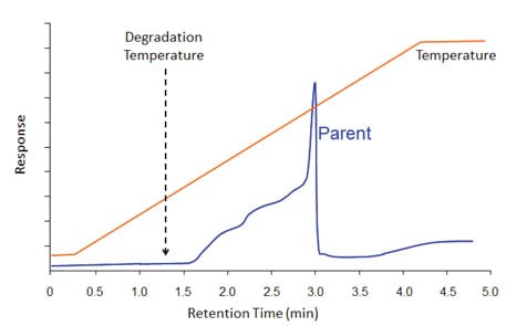 Figure 4: There is no degradation from the inlet in this example because a cool on-column inlet was used. However, there is degradation (to an earlier-eluting compound) that happened when the compound’s degradation temperature was exceeded during the temperature program. Some of the parent compound made it through the column, as indicated by the sharp peak at the end of the degradation plateau.
Figure 4 illustrates what it might look like when a compound decomposes along the column. Let’s say a compound is known from thermal analysis data to thermally decompose at temperature X. Since we have that information, we choose to use a gentle sample introduction technique; a cool on-column inlet. The injection happens at low temperature so there is no thermal decomposition in the inlet. However, the elution temperature of the parent peak is above its decomposition temperature. So decomposition happened in the column. Since the decomposition is not instantaneous, decomposition products were created over a long time period (relative to normal peak widths) until all parent compound is either gone or eluted from the column. In the example of Figure 4, some parent compound remained and eluted at its characteristic elution temperature. In this example, the decomposition product was less-retained than the parent, so the ugly blob occurred on the low-temperature side of the parent peak. Sometimes, there is no parent compound left, so one sees only an ugly blob.
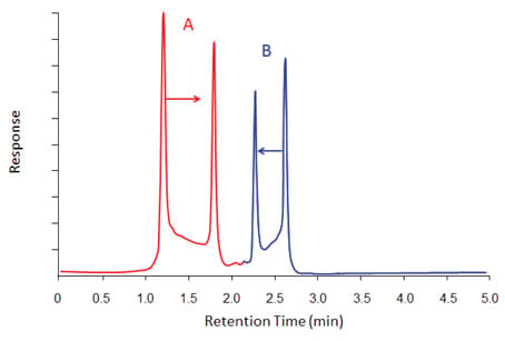
Figure 5: Degradation occurring both from a hot inlet (existence of a sharp degradation peak) and along the column (the continuous bridge between the parent and degradation peak). The degradation peak in Group A elutes at later than the parent and the one in Group B elutes earlier.
Figure 5 shows a combination of degradation occurring in both inlet and along the column. In one case, the degradation product is more retained than the parent and in the other it is less retained. The combination of the bridges between the parent and the degradation peaks and the normally-shaped front and back sides are very characteristic of degradation and are easy to spot. The bridge usually is highest on the side of the parent compound. The height of the bridge between the associated peaks is an indication of the amount of decomposition happening along the column relative to that in the inlet (the higher the bridge, the more the decomposition in the column).
If you suspect sample decomposition, what can you do? For inlet related decomposition, the objective is to reduce thermal stress and catalytic activity.
- Reduce inlet temperature 75 oC. Many people use inlet temperatures that are far above what they need to be. If things look better, reduce it another 75 oC. Verify that the lower temperature did not degrade performance metrics for the other sample components (especially the late eluters). Pick the lowest inlet temperature that still meets method requirements.
- Trim the column and do inlet maintenance, including replacing the current liner with a new one of the same type.
- Try to find a more inert liner (including taper at the bottom).
- Remove the glass wool in the liner. Glass wool can be quite active. Yes, reproducibility will probably be worse without the wool. Pick your battles.
- Decrease residence time of sample in inlet; use the Pressure Pulse technique, increase split ratio, use a liner with smaller volume.
- Switch to a programmable temperature inlet (PTV or COC). Using a lower initial temperature during injection, with a mild inlet temperature ramp will often transfer the labile compound to the column before the inlet reaches the compound’s degradation temperature.
For decomposition that happens in the column, the objective is to minimize activity in the column and elute the parent before its decomposition temperature is reached, if possible.
If using a packed column, use a more inert support, use more inert tubing, switch to a fused-silica capillary column counterpart.
Increase the column flow either during the full run or employ an aggressive flow/pressure program after important earlier peaks requiring more optimal flow have eluted.
Slow down the temperature program rate at a given column flow rate. Compounds elute at lower temperatures when slower ramp rates are used.
Use a column with a thinner stationary phase (higher β). Remember that when you reduce film thickness by ½ (double β), elution temperatures in a temperature program will be approximately 25 oC lower.
If all else fails, then one must consider derivatizing the compound to form a more stable compound that can survive GC, or one switches to an alternate technique altogether, like SFC or HPLC.
This blog article series is produced in collaboration with Dr Matthew S. Klee, internationally recognized for contributions to the theory and practice of gas chromatography. His experience in chemical, pharmaceutical and instrument companies spans over 30 years. During this time, Dr Klee’s work has focused on elucidation and practical demonstration of the many processes involved with GC analysis, with the ultimate goal of improving the ease of use of GC systems, ruggedness of methods and overall quality of results. If you have any questions about this article send them to techtips@sepscience.com


