If you have a low-pressure-mixing system on your HPLC, the solvents are blended using a proportioning valve. Usually this mixes up to 4 different mobile phase components. The pump delivers at a constant flow rate, for example, 1 mL/min, and the various proportioning valves open and close to allow the right proportion of each solvent to enter the mixer. For example, if you have programmed the HPLC to deliver 75% buffer (the A-solvent) and 25% methanol (MeOH, the B-solvent), the valves would open A-B-A-B-A-B… in a 75:25 ratio of opening times. These pulses of A and B are mixed, drawn into the pump, and delivered to the column. To deliver a gradient, the ratio of the opening times of the various proportioning valves will change during the gradient to change the mobile phase composition.
Obviously, accurate delivery of the desired mobile phase mixture depends on the proper operation of the proportioning valves. It is prudent to check the performance of the proportioning-valve system occasionally, usually during a performance qualification session once or twice a year.
The gradient proportioning valve (GPV) test is a simple way to make sure the various components are working properly. The setup is as follows:
• remove the column and replace it with a piece of capillary tubing; ≈1 m of 0.125 mm i.d. (0.005-in.) PEEK tubing works quite well for this.
• place water in the A-reservoir; the A- and C-solvent inlet lines go in this reservoir.
• place water plus 0.1% acetone in the B-reservoir; the B- and D-solvent lines go in this reservoir.
• set the UV detector to 265 nm, where acetone absorbs strongly.
• set the flow rate to 2 mL/min
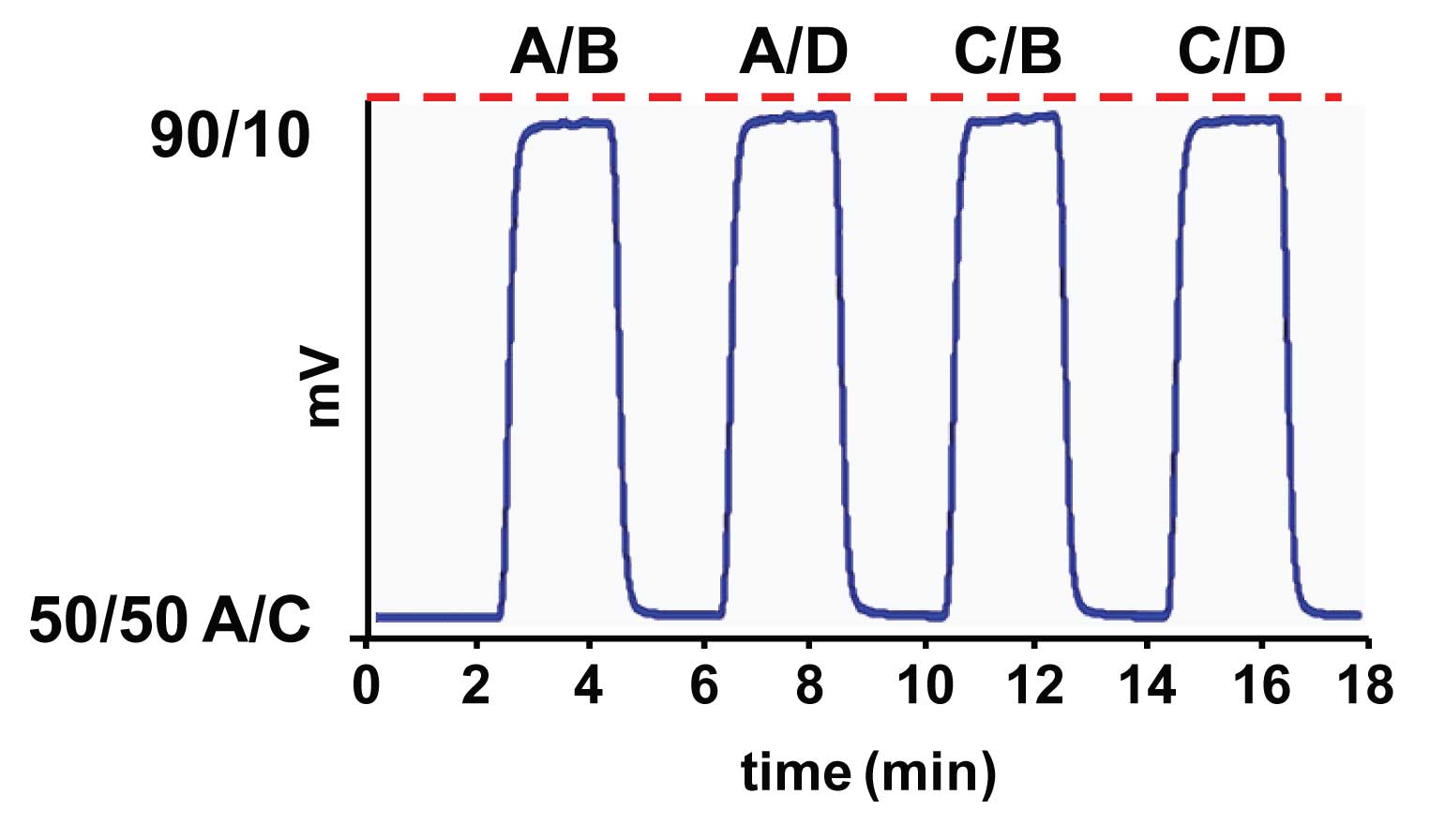
• program a series of steps as shown in Figure 1, 2 min per step: 50/50 A/C, 90/10 A/B, etc.

Figure 1
If all is working well, you should see a plot similar to that of Figure 1. When acetone is present (mixtures containing B or D), the signal will rise relative to the water-only (A/C) blends. Each of the acetone mixtures should be the same, so the plateau height and the shape of the “peaks” should be the same in each case. A properly functioning system should have the plateau heights within 1-2% of each other – if the range in heights differs by more than 5%, corrective action should be taken. In my experience, the plateaus will be very close, as is the case for Figure 1, or there is an obvious failure, as we’ll see in next week’s HPLC Solutions.
Even when it is working properly, the proportioning system may not be perfect. Look carefully at Figure 1 and you can see that all four peaks are not exactly the same. There is a little difference in the rounding at the front and back edges of the top, so some look more or less square than others. This is a minor issue in the present case, and my guess is that this has to do with the relative location of the various solvent inlets on the mixing manifold. For example, if the inlets are opposite each other, the mixing and washout of the mixer may be more or less efficient than if the inlets are offset by 90º.
This GPV test is a simple test to run, and may identify problems with the proportioning system that might otherwise be overlooked. We’ll see an example of this in next week’s HPLC Solutions.
This blog article series is produced in collaboration with John Dolan, best known as one of the world’s foremost HPLC troubleshooting authorities. He is also known for his research with Lloyd Snyder, which resulted in more than 100 technical publications and three books. If you have any questions about this article send them to TechTips@sepscience.com


