In a previous article (Dwell Differences, HPLC Solutions #85) we saw an example of how the appearance of a chromatogram could change when a gradient method was run on two HPLC systems of differing dwell volume. In this article we’ll look at a simple way to measure dwell volume.
The Setup
The dwell volume comprises all the system volume from the mixer to the head of the column. This is easily measured using the conditions shown in the sidebar. Remove the column and replace it with a piece of capillary tubing. A 1-m piece of 0.125 mm (0.005-in.) i.d. tubing works well for this; for example, a meter of red PEEK tubing can be used. This connects the autosampler to the detector, provides sufficient back-pressure so that the pump will work well, and has negligible volume (≈ 12 µL). Place water in the A-solvent reservoir and water + 0.1% acetone in the B-reservoir; the acetone will provide UV absorbance to enable us to measure the dwell volume. Set the detector at 265 nm, where acetone absorbs strongly. Then run a gradient that is typical of the gradients you run in the lab. In the present example, I’ve chosen a 0-100% B gradient run over 20 min at 2 mL/min. This should be OK if you run gradients of 10–60 min duration at 1-2 mL/min; if you typically run shorter or longer gradients, you might choose conditions that more closely mimic normal gradient conditions. You should leave the injector in the inject position during this measurement, because the injector loop volume is part of the dwell volume.

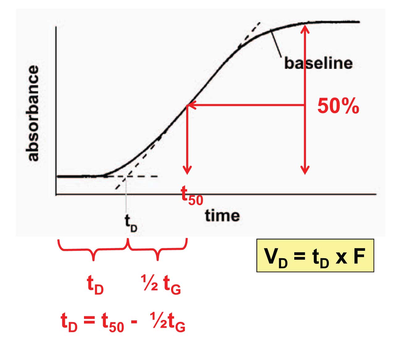
Figure 1
The Measurements
Once the gradient is run, you should see a “chromatogram” that looks similar to that shown in Figure 1, where the initial flat baseline represents 0% acetone (100% A) and the final flat baseline is 0.1% acetone (100% B) and the sloping line is the transition between the two. There are two common ways to measure the dwell volume from this tracing.
The first technique is to print the chromatogram and use a straight-edge to draw a line through the gradient portion of the curve, extending below the baseline (dashed line, Figure 1). Next, extend the initial baseline until it intersects this line. The intersection represents the dwell time (t D) of the system. Dwell time is converted to dwell volume (V D) as V D = t D x F, where F is the flow rate. So if t D = 0.85 min and F = 2 mL/min, V D = 1.7 mL.
The alternate measurement technique is the one I prefer, shown in red, because it can be done right on the computer monitor. Measure the offset between the low and high baseline and find the midpoint. Extend a line from the midpoint horizontally until it intersects the rising baseline. From this intersection, drop a line vertically to the time axis. Subtract half of the gradient time, (20 min / 2 = 10 min in the present case). The remaining time is the dwell time, which can be converted to dwell volume the same way as we did above.
Once the dwell volume is measured for an HPLC system, it should not change over time unless major changes in the system plumbing are made. However, this is a simple measurement to make and is worth making each time a system performance qualification is performed, such as every 6 or 12 months, because sometimes it will highlight other problems in the system.
Next week we’ll look at another use of the dwell-volume test in diagnosing potential problems.
This blog article series is produced in collaboration with John Dolan, best known as one of the world’s foremost HPLC troubleshooting authorities. He is also known for his research with Lloyd Snyder, which resulted in more than 100 technical publications and three books. If you have any questions about this article send them to TechTips@sepscience.com


